SPI Protocol
SPI signal lines, transfer modes, frames and VHDL implementation points.
What is SPI?
The SPI (Serial Peripheral Interface) protocol is a synchronous serial protocol developed by Motorola in the 1980s. It is widely used in embedded systems for communication between a microcontroller or FPGA and peripherals such as sensors, ADC/DAC converters, Flash memories, or displays.
Key characteristics:
- Synchronous: a shared clock (SCK) drives all transfers
- Full-duplex: simultaneous transmission and reception
- Master/Slave: the master generates the clock and selects the slave
- No addressing: selection is done via a dedicated SS_N signal
SPI Signals
| Signal | Direction | Description |
|---|---|---|
| SCK | Master → Slave | Serial Clock |
| MOSI | Master → Slave | Master Out Slave In |
| MISO | Slave → Master | Master In Slave Out |
| SS_N | Master → Slave | Slave Select, active low |
With multiple slaves, the master has one SS_N signal per slave. MOSI, MISO, and SCK are shared (bus).
SPI Modes (CPOL / CPHA)
SPI defines 4 modes based on two parameters:
- CPOL (Clock Polarity): idle state of SCK - 0 = low, 1 = high
- CPHA (Clock Phase): sampling moment - 0 = leading edge, 1 = trailing edge
| Mode | CPOL | CPHA | Sampling | Description |
|---|---|---|---|---|
| 0 | 0 | 0 | SCK rising edge | SCK idle low, sample on rising |
| 1 | 0 | 1 | SCK falling edge | SCK idle low, sample on falling |
| 2 | 1 | 0 | SCK falling edge | SCK idle high, sample on falling |
| 3 | 1 | 1 | SCK rising edge | SCK idle high, sample on rising |
Mode 0 (CPOL=0, CPHA=0) is the most common. The beginner SPI master exercises use it; the SPI slave exercise uses mode 1.
SPI Frame
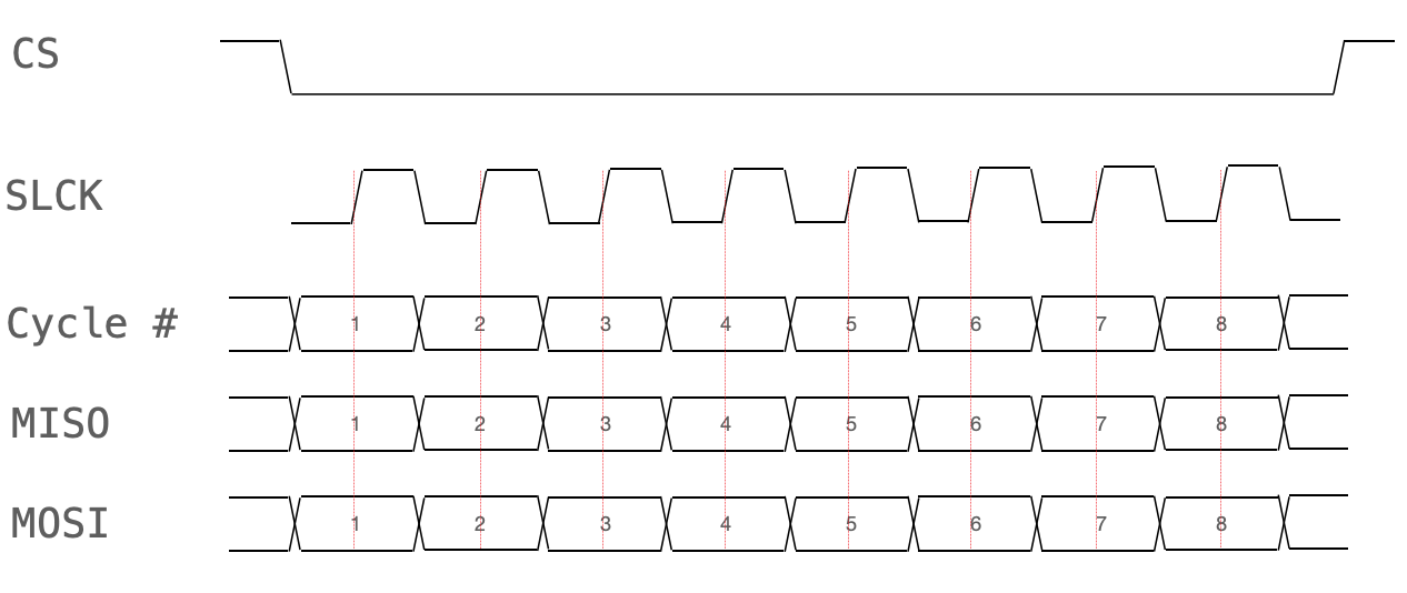
A SPI transaction proceeds as follows:
- Master asserts SS_N low to select the slave
- Master generates SCK pulses
- Each SCK cycle transfers 1 bit in each direction (MOSI and MISO)
- Data is transmitted MSB first (most common convention)