Building a SystemVerilog Testbench from Start to Finish | FPGA Pour Tous
Summary
Building a SystemVerilog Testbench from Start to Finish
Build a runnable testbench: instantiate the DUT, generate clock and reset, apply scenarios, check outputs, and finish with a trustworthy verdict.
The intended result
A testbench is simulation code that places the design under test, the DUT, in selected situations. It should produce a verdict without requiring manual inspection of every waveform.
By the end of this chapter, the testbench will be able to:
instantiate and connect the DUT;
generate clock and reset;
apply stimulus at the right time;
calculate or store expected results;
compare expected and observed values automatically;
detect a stall and finish with PASS or FAIL.
The testbench file is commonly named something like pulse_counter_tb.sv. It is not synthesizable and does not become hardware in the FPGA.
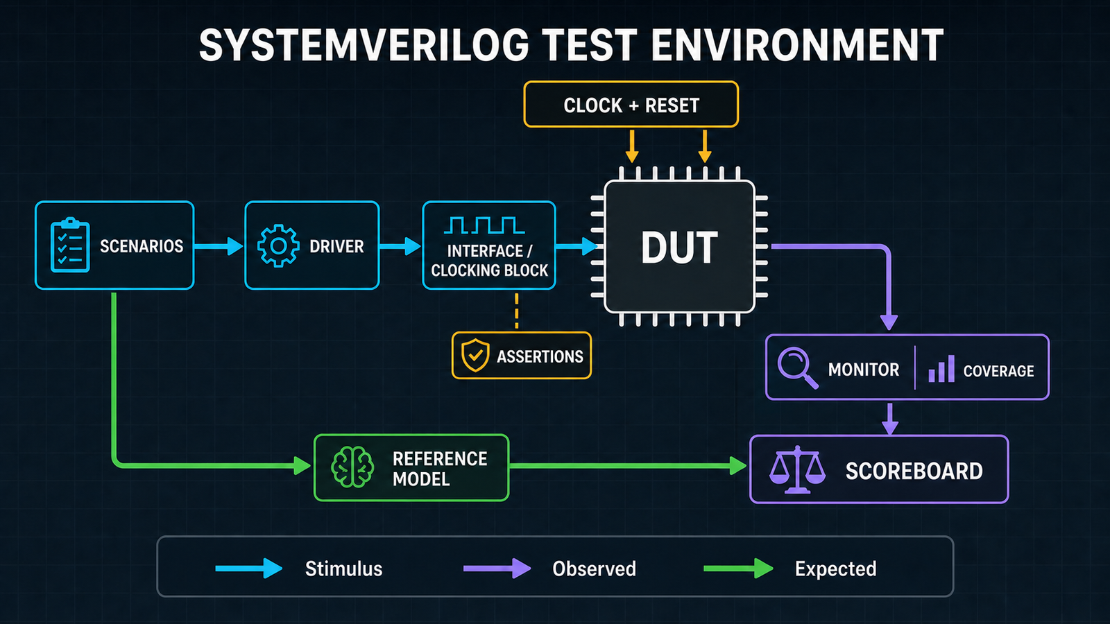
The cyan path applies stimulus to the DUT. The violet path reconstructs what actually happened. The green path computes the expected result independently, and the scoreboard compares both paths.
Start from the contract, not the internals
The example verifies a 4-bit counter named pulse_counter. Its contract is intentionally short:
Port
Role
i_clk
the counter acts on each rising edge
i_rst_n
active-low asynchronous reset
i_enable
the counter advances at 1 and holds at 0
o_count
4-bit result, wrapping from 4'hF to 4'h0
Before any SystemVerilog is written, this table identifies the mandatory scenarios: reset, hold, counting, consecutive operations, and wraparound. The testbench must not read internal counter signals to predict the result.
The minimum structure
The test module has no ports. It declares connection signals, instantiates the DUT, and contains the simulation processes.
timeunit and timeprecision keep delays independent from a directive in another source file. Named connections such as .i_clk(clk) are safer than positional connections when the DUT port order changes.
Reset starts asserted, so the DUT sees a defined condition from its first simulation events. The test sequence will release it explicitly.
A complete self-checking testbench
The complete version below drives inputs on the falling edge, away from the rising edge used by the DUT. It also checks the output on a falling edge, after register updates from the previous rising edge have completed.
module pulse_counter_tb; timeunit 1ns; timeprecision 1ps; localparam time CLK_PERIOD = 10ns; logic clk = 1'b0; logic rst_n = 1'b0; logic enable = 1'b0; logic [3:0] count; int unsigned checks = 0; int unsigned errors = 0; pulse_counter dut ( .i_clk (clk), .i_rst_n (rst_n), .i_enable (enable), .o_count (count) ); always #(CLK_PERIOD / 2) clk = ~clk; task automatic check_count( input logic [3:0] expected, input string case_name ); checks++; count_matches_a: assert (count === expected) begin // Success: the check counter is sufficient. end else begin errors++; $error("%s: count=%h, expected=%h, time=%0t", case_name, count, expected, $time); end endtask // The first call occurs on a falling edge. Every call returns on the // following falling edge, ready for the next scenario. task automatic step_and_check( input logic next_enable, input logic [3:0] expected, input string case_name ); enable <= next_enable; @(negedge clk); check_count(expected, case_name); endtask initial begin : test_sequence logic [3:0] expected; expected = '0; // The first rising edge occurs while reset is asserted. @(negedge clk); check_count('0, "initial reset"); rst_n <= 1'b1; // Three consecutive increments. repeat (3) begin expected++; step_and_check(1'b1, expected, "enabled count"); end // enable=0 must hold the current value. step_and_check(1'b0, expected, "hold"); // Thirteen increments from 3 must pass through 15 and wrap to 0. repeat (13) begin expected++; step_and_check( 1'b1, expected, $sformatf("wraparound test, expected=%0d", expected) ); end // Also verify reset after a period of activity. repeat (3) begin expected++; step_and_check(1'b1, expected, "prepare active reset"); end rst_n <= 1'b0; enable <= 1'b1; @(negedge clk); expected = '0; check_count(expected, "reset during activity"); rst_n <= 1'b1; enable <= 1'b0; if (checks == 0) $fatal(1, "FAIL: no checks executed"); if (errors == 0) begin $display("PASS: %0d checks", checks); $finish; end $fatal(1, "FAIL: %0d error(s) in %0d checks", errors, checks); end initial begin : watchdog #(30 * CLK_PERIOD); $fatal(1, "FAIL: timeout at %0t", $time); endendmodule
The expected-value model is the variable expected. It follows the counter requirement without copying the RTL architecture. Its 4-bit type naturally models wraparound from 15 to 0.
Why the edges are separated
If the testbench drives enable on the same rising edge where the DUT reads it, process scheduling can create a race: the DUT may see either the old or new value.
This small DUT uses a simple convention:
drive after a falling edge;
let the DUT act on the next rising edge;
check on the following falling edge, after the DUT's nonblocking assignments have completed.
This convention needs no arbitrary #1ns delay for a synchronous check. A DUT that works on falling edges, uses several clocks, or has a more precise protocol needs a different documented timing strategy.
Compare all four states
The checker asserts count === expected. Case equality also compares X and Z values and always returns true or false. Because the expected value contains only 0 or 1 here, an unknown output becomes a clear failure. The equivalent error-branch form would be if (count !== expected).
An assertion is suitable when a mismatch should stop the run immediately:
The example uses $error to continue and collect several mismatches. The final $fatal still gives the simulation campaign a failing status.
Hide protocol details in tasks
step_and_check hides low-level timing details. The scenario states what to test, while the task decides when to drive and observe. A bus testbench can use the same idea with write, read, or send_packet tasks.
A small task may combine driving and checking. As the protocol grows, separate the driver, monitor, reference model, and scoreboard so that one coding mistake cannot generate both stimulus and verdict.
Move to a clocking block
For a richer synchronous interface, a clocking block centralizes directions and drive or sample timing.
The test now synchronizes with @(bus.tb_cb), drives bus.tb_cb.enable <= ..., and reads bus.tb_cb.count. It should not bypass the clocking block by accessing the same signals directly. By default, a #1step input is sampled just before the current edge, and a #0 output is driven at the current edge. Clocking-block outputs are driven with nonblocking assignments.
Check clocking-block support in the selected simulator. The complete testbench above remains usable without this construct because it follows a documented edge convention.
Separate the physical bench from the timing scenario
In a small test, one module and an opposite-edge convention remain very readable. For a class-based environment, the following separation scales better:
a module instantiates the DUT, interfaces, and clock generator;
an interface groups signals, modports, and clocking blocks;
a program automatic, when the simulator supports it correctly, contains the scenario and prevents its variables from being static by default;
classes access the physical interface through a virtual interface.
A program cannot contain an always process, so the clock remains in the module. Completion of all its initial blocks may end the simulation; the driver, monitor, watchdog, and drain sequence must therefore be coordinated before that point.
Adding #0 or #1 to a few statements is not a general solution to races. #0 guarantees no stable ordering between threads, and #1 depends on the time units. An explicit sampling convention or a clocking block expresses the timing protocol itself.
Adapt the pattern to a combinational DUT
A purely combinational DUT has neither clock nor reset. The task applies inputs, lets combinational events settle, and then checks the output:
The delay belongs in the testbench, never in the combinational RTL. It must exceed the simulated delays that need to propagate and must not be used to conceal a synchronization mistake.
Timeout, summary, and waveforms
The watchdog prevents an infinite wait from running without a verdict. Set its limit comfortably above the normal test duration but low enough to expose a stuck protocol quickly.
In a layered environment, reporting follows a drain period: the generator stops, then transactions that have already been accepted pass through the driver, DUT, monitors, and scoreboard. Wrap-up finally checks that no expected response remains outstanding and publishes the generated, observed, compared, and error counts.
Waveforms remain useful for diagnosis. A VCD-capable simulator can use:
initial begin $dumpfile("pulse_counter.vcd"); $dumpvars(0, pulse_counter_tb);end
Open the trace after a failure to understand its timing context. The trace does not replace comparisons or the final summary.
Compile and run
With Icarus Verilog, enable SystemVerilog mode and select the top module explicitly:
When a project uses packages or interfaces, list them before files that depend on them. A script or file list keeps compilation order consistent between runs.
Checklist before trusting the test
The test module has no ports and the simulator launches the intended top.
Widths, signedness, names, and reset polarities match the DUT.
Inputs are initialized before their first use.
Drive timing is separate from the edge where the DUT samples inputs.
Every important requirement has at least one scenario and one check.
Boundaries, consecutive operations, reset during activity, and illegal values are considered.
An unexpected X or Z fails the test.
The watchdog, check count, and final summary are active.
The expected model comes from the specification, not a copy of the RTL.
Key takeaways
A trustworthy testbench connects stimulus, expected value, check, and verdict.
Clock and reset are part of the verification scenario.
A documented edge convention or clocking block avoids races with the DUT.
#0 and #1 do not replace a defined synchronization scheme.
Tasks keep scenarios readable by hiding low-level protocol timing.
!==, $error, $fatal, a watchdog, and a check counter make failures visible.
Waveforms explain a failure that automatic checks have already detected.